
This work is licensed under a Creative
Commons Attribution 3.0 Unported License.
The ANSI Type-2 opto-coupler simply converts an RS232 serial connection from electrical signals to infrared signals. There is no modification whatsoever of the signals. Another technology called IrDA is similar but NOT THE SAME and is NOT COMPATIBLE. Given how basic the operation of the opto-coupler is I was shocked to discover that they cost $100's so I decided to make my own and you can too.
This project requires advanced ninja soldering skills, you have to solder very tiny surface mount components onto a PCB. If you have not soldered before, then this is not the project for you. You will need a fine-tip soldering iron and uncaffinated motor skills. A reasonably long index finger nail is also of great use holding the tiny components down while soldering, so let that one grow out a little before starting the project.
Overview
There are two parts to the project, the printed circuit board (PCB) and the enclosure. The PCB can be ordered for a nominal amount from batchpcb.com, or you are welcome to download the gerber files and have it made somewhere else. The components can be purchased as a project from mouser.com. There are no specialized components in the project. However, mouser tends to churn generic products, so the basic diode part number that was fine last year, isn't available this year. Therefore CHECK THE AVAILABILITY of every component on the project list before purchasing it otherwise you may wait 6 months to receive a generic signal diode when dozens of compatible parts were available to ship immediately. The enclosure consists of two pieces, the body and the lid. It can be made by downloading and 3D printing these STL files. The best results I've gotten from 3D printing were using the Polyjet Blue HD from ZoomRP. It cost approximately $130 to get both pieces printed, which is expensive, but less than the price of a new opto-coupler.
Project Files
| Document Description | Source | Document |
| Circuit Schematic, including parts list and theory of operation | Project from Mouser | ANSI T2 Schematic.pdf |
| Gerber files for PCR (two sides + silk screen & solder mask) | PCB from BatchPCB | OC_r2p1.zip |
| 3D stereo lithography files for 3D printing of enclosure body and lid | Recommend ZoomRP | OC_STL_r2.zip |
| Component data sheets | Datasheets.zip |
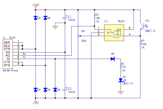
Schematic of ANSI Type 2 Optical Probe (Opto-Coupler)
Theory of Operation
This
circuit converts RS232 signals from electrical to IR optical pulses. It
is designed specifically to connect to the ANSI 12.18 optical port found
on many American electrical utility meters. However, it is a completely
generic circuit and can be used for almost any RS232 over IR application.
The data polarity is as follows:
LED on, start bit, space, logical 0
LED off, stop bit, mark, logical 1, quiescent state
The circuit is powered from the PC serial port outputs; DTR, RTS &
TD. DTR and RTS are handshake signals, typically they are both at +12V,
but this can vary depending on how the software configures the PC serial
port. When DTR or RTS are at +12V they charge C1 through D2 and D6 respectively.
When they are at -12V they charge C2 through D7 and D3 respectively. The
TD line is mostly at -12V, so it is used to also charge C2 through D4.
This guarantees a negative supply, because in many applications DTR and
RTS won�t go negative. The actual voltage generated on the supplies
will depend on the levels to which the particular PC or USB dongle drives
the signal lines.
Connecting the signals DSR (Data Set Ready) and DCD (Data Carrier Detect)
to the DTR (Data Terminal Ready) and the CTS (Clear To Send) to the RTS
(Ready To Send) takes care of any hand shaking the PC software may want
to do. Diode D5 protects the LED (D1) when TD is lower than -5V, because
its maximum permitted reverse voltage is only 5V. R1 limits the current
through D1 when TD is high.
The non-inverting input (pin-4) to the comparator U1 is pulled to the
negative supply by R3 when the photo-transistor PT1 is off. When PT1 detects
infra red light and switches on, it pulls the input to the positive supply.
The potentiometer R4 is used to set the threshold at which the comparator
switches. Typically it will be adjusted so that the inverting input (pin-3)
is around 0V. Use an oscilloscope to set this voltage at the midpoint
of whatever swing is observed at pin-4 when PT1 detects IR (or just leave
it centered). Resistor R2 is just a pull-up resistor for the open-collector
output of the comparator.
The circuit is designed to be operated remotely at the end of a long cable. As an 8-conductor cable was required, the cheapest highest quality cable readily available is CAT5 or CAT6 network cable. Therefore, the circuit is designed to have a standard 8-pin RJ45 socket (like a typical Ethernet socket). There is a standard called EIA-561 that defines the pin-out to use for RS232 on RJ45 connectors. This is the pin-out used in this schematic. Typically the PC will have a 9-pin D-Type connector. Therefore you will need a 9-pin D-Type Female �Modular to Sub-D� adapter kit to make the connection to the PC.
 Completed ANSI T2 Printed Circuit Board click to embiggen |
PCB Construction Notes Start with the IC U1, then the diodes, the resistors, the potentiometer, the capacitors and finally the socket. To solder on a component, first melt a very small amount of solder onto one PCB pad of its footprint. Then position the component holding it down with your index finger nail (kept slightly long). You could also use a tweezers, but your finger nails works better. Then heat the component pin placed over the pad that you put solder on earlier. This will solder than one pin to the PCB and keep the devices positioned while you solder its other pins. The capacitors are polarized, make sure you solder then on the correct way. Don't solder the LED and photo transistor just yet, unless it's just temporary to test the circuit out. |
Testing
The opto-coupler is powered from the serial port, so it will only work if its hooked up to an active (i.e. open) serial port. The easiest way to do this is using a terminal emulator program like Realterm. Once you're hooked up and the port is open it should look something like this:
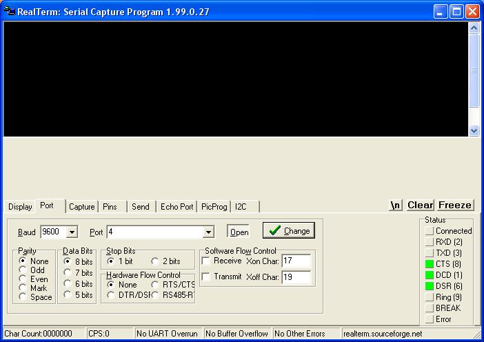
The CTS, DCD & DSR bits are all active because they're hooked up to the DTR & RTS signals. Now check that the +ve and -ve rails (which are easy to check on the ends of the two capacitors) are correct. They should be about+/- 5V for a USB to serial dongle and perhaps +/- 9V for a standard PC serial port. If you solder the LED in and view it through the screen of a digital camera, you will see the IR flash when you transmit some data. You can use the "Send" tab of Realterm to do this.
|
 The exterior of the enclosure showing the holes for the LED & photo transistor There is a hole in the enclosure lid to facilitate attaching a label requesting the meter reader to replace the opto-coupler when done. |

 |
Install the two magnets, the LED and the photo transistor. The LED is clear, the photo transistor is black. The enclosure is designed to help you keep the polarity correct. The magnets are 3/8" diameter x 1/8" thick and will press fit into the recesses in the enclosure. Buy the strongest magnets you can. Seal everything in with a layer of silicone glue, but be careful not to get glue on the component leads. |
 |
Place a bead of silicone on the enclosure underneath and on each side of the RJ45 socket's position, then slip the PCB down onto the leads of the LED & photo transistor. Solder the connections and snip the excess leads. Then fill the area above the circuit board with silicone glue. Try and seal in everything to keep water away from the circuitry and the back of the RJ45 socket. Finally put a bead of silicone across the top of the socket and around the inside of the lib, then press the lid on. At this point the electronics inside the opto-coupler should be completely sealed against water. This picture also shows the CAT5 cable that is used by the design and the 9-pin D-Type Female �Modular to Sub-D� adapter to convert an RJ45 plug into a female 9-pin D-Type connector suitable to plug into a PC serial port. RS232 interfaces are extremely robust, this probe should easily operate over hundreds of feet of CAT5 cable. |